An inductor is a circuit component which is capable of producing a voltage across its terminals in response to a changing current flowing through it. The voltage occurs as a result of magnetic induction in which the time varying magnetic field due to the current induces an electromotive force in the inductor. Not surprisingly inductors are usually just coils of wire. The windings are necessary to enhance the flux linkage which then allows a larger inductance to be produced in a smaller size. To think about this, note that the effect of winding a wire into a coil is simply to multiply the coil area by the number of turns, N. Thus a coil when unravelled has N x the coil area.
Mathematically, the electromotive force is given by V = LdI/dt. Inductive reactance increases with frequency due to the increase in the rate at which the flux changes. Modest or low value inductive reactances for high frequency may require the inductor to consist of no more than a straight wire as given by the expression for the inductance of a wire.
The unit of inductance is the "Henry" and the impedance is given by Z = j&omega L where L is the inductance. Typical values of L lie in the range of nH to H. A value of 1 nH corresponds to a wire of about 1 mm length and 1 mm radius. A 10 H inductance is as big as a small car and would be useful mainly as a filter for a very large power supply.
In this course where radio circuits in the range of 10 MHz to 1 GHz are studied, the inductances that you will typically use are in the range of 10 nH - 10 &mu H.
The inductance of a coil at low frequencies (where rf effects are negligible!) is given by the following formula:
L = 0.394r2N2/(9r + 10l)(&mu H),where r = the radius of the coil (cm) and l = the length of the coil (cm). Whereas capacitors and resistors for each occasion are relatively easy to find due to the variety of commercially available components, in some cases inductances may be easier to build from wire. However there are tricks here as well. The figure shows an electromagnetic artist's view of an inductor.
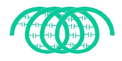
As can be seen, an inductor produces a voltage from turn to turn and from our previous ideas about capacitance we can bet that adjacent turns act like the plates of a capacitor. The main problem with inductors therefore is stray distributed capacitance from turn to turn. Loosely then, one may model the inductor as follows
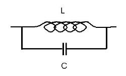
Such a circuit produces a parallel resonance as we have seen for resistors.
The concept of distributed capacitance is complicated in the same way as it is for transmission lines. In a twin wire transmission line, uniformly distributed capacitance and inductance leads to a wave which propagates along the line at a speed which is always equal to the speed of light in the material dielectric separating the lines. The same is true for the above inductor provided the turns are not too closely spaced where mutual inductance becomes important.
This means that the parallel resonance is often not really due to the above simplified parallel LC circuit at all, but is rather a resonance of a wave along a weird kind of "transmission line" that is separated from earth i.e. its return path is in an image in the earth. In reality such an inductor is better termed a "helical antenna".
An inductor is therefore (unfortunately) quite a successful and interesting radiating system. The resonance is due to a current flowing along the helix with a total of 1/4 of a wavelenegth along the outstretched wire, the radiation is "broadside" (monopole antenna) meaning that it is in the equatorial plane of the helix. Moreover the system occupies much less space than the stretched out wire or monopole itself and many commercial "whip antennas" are in fact inductive coils or helices. This radiation leads to a loss resistance referred to as antenna radiation resistance. A large antenna radiation resistance is good for antennas but is clearly bad for inductors as it produces both losses and Radiofrequency Interference (RFI). One solution is to enclose the inductor inside a metal can exposing only its terminals to the outside world. In this case the inductor cannot radiate and its losses can be low provided that the can itself is not lossy. Such a can enclosing a coil is also called a helical resonator.
One final trick to remember about inductors as is true for transmission lines and antennas, is that the exact nature of the above resonance depends on how the inductor is driven. The 1/4 wave resonance occurs if one end of the inductor is grounded and the other end is excited. A half wave resonance would occur if driven in push-pull. In either case the inductor becomes very sensitive to the touch and is useless for most purposes. Clearly, if inductive behaviour is desired then you should keep well below 1/4 wave resonance. However inductors that resonate can replace LC resonator circuits. In this case however such helical resonantors have to be kept inside a shield.
Internal wire losses and radiation limit the Q = X/R, where X is the inductive reactance (&omega L) and R is the series loss resistance. For a resonant circuit the Q = fc/(fU3dB - fL3dB), where fc is the resonance frequency and fU3dB, fL3dB are respectively the lower and upper 3dB frequencies. We say more about this in matching networks.
Ex. 7. Use the Vector Network Analyser to perform measurements of three home made air core inductors of approximate values 200 nH, 1 &mu H and 10 &mu H from 1 to 100MHz.
(i) How does the impedance depend on the length of the wires used to make the inductor?
(ii) Measure the Q of the inductors at resonance.