The impedance of a wire is divided into internal
and external impedance, Z = ZInt +
ZExt The internal impedance is due to the
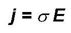
conductivity (1/resistivity) of the metal. Metal conductivities are
always real numbers expressing the ratio of the current per unit area
at a point in the metal to the local electric field at that point.
For metals it can be shown that electric fields originating outside the metal only exponentially penetrate a distance &delta = (&mu o &pi f &sigma)-1/2, the skin depth (see Ramo for details and much is explained in lectures).
One consequence of this is that the resistive and inductive parts of ZInt are equal. The internal impedance is expressed in terms of the impedance by width and per unit length of the surface (impedance per square). It is given by Zs = Rs(1 + j) where Rs = (&pi&mu0f/&sigma)1/2 and where &mu0 is the free space permeability (= 4&pi x 10-7 Webers/meter) and f the frequency. Impedance per square is defined by dividing the electric field at the air metal interface by the current per unit width across the interface. Impedance per square therefore has the dimensions of Ohms. If one has a metal rod then its internal impedance can be found by multiplying its impedance per square by its length and dividing by its width.
Since most systems operate on an impedance level of order 50&Omega, the internal impedance is negligible under most "hook up wire" situations. See the exercise below.
Much worse is the external inductance (inductance is discussed here) and in lectures). For a straight piece of cylindrical wire, the self inductance is given by (Grover),
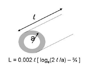
where a and l are the radius and length of the wire (in cm) and L the inductance in microHenries. This expression ignores the return path of the current and assumes that the length of the wire is much smaller than the wavelength (c/f where c = 3 x 10⁸ m/s is the speed of light). If the return current path is through a similar wire that is not too close by, then the total self inductance in the circuit would be twice this value.
The following conclusions can be drawn:
Before making a track on a print circuit board (PCB) that carries a radiofrequency current, care should be taken to ensure that its inductance does not alter the desired impedance. For this you can use Grover's formula.
At UHF, inductors may well be tracks on a PCB. However to calculate the inductance here one must take into account the return path due to any copper plane beneath the board and a better model would be to use a transmission line section.
Often the best solution to an earthing problem lay not in the use of wire straps.
Ex. 1. Show that for f = 1 GHz, copper wire of .2 mm radius, and length 50 mm has an internal impedance given by Z = 0.3(1+j)&Omega .
Ex. 2. Show that a strand of copper wire of .2 mm radius and length 50 mm has an external inductance of L = 55 nH. Calculate the impedance due to the external inductance at 1 GHz and compare to the internal inductance calculated above. Which is the largest?