next up previous contents index

[ENGN2211 Home]

Circuit Analysis

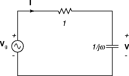
Let's analyse the steady state AC response of the circuit of Figure 33 using phasors. The phasor circuit is shown in Figure 37. Here, ${\mathbf V}_g = 5\angle 0$ V.


Figure 37: RC phasor circuit showing AC impedances.
\begin{figure}
\begin{center}
\epsfig{file=images/acimg5.eps}\end{center}\end{figure}

By KVL and Ohm's law, we have

\begin{displaymath}{\mathbf V}_g = {\mathbf I} (1+\frac{1}{j2}) ,
\end{displaymath}

and so

\begin{displaymath}{\mathbf I} = \frac{{\mathbf V}_g}{1+\frac{1}{j2}}
= \frac{j2 \times 5\angle 0}{1+j2}
\end{displaymath}

or

\begin{displaymath}{\mathbf I} = 4+j2
= 2\sqrt{5} \angle 26.6^\circ
\ {\rm A} .
\end{displaymath}

Then by Ohm's law,

\begin{displaymath}{\mathbf V} = {\mathbf I} \frac{1}{j2}
= 1-j2 \ {\rm V} ,
\end{displaymath}

or

 \begin{displaymath}{\mathbf V} = \sqrt{5}\angle -63.4^\circ = \sqrt{5}e^{-j63.4^\circ} \ {\rm V}
\end{displaymath} (47)

in agreement with (46) and (45).

We obtain the real voltage by

 \begin{displaymath}v(t) = {\rm Re} ( \sqrt{5}e^{-j63.4^\circ} e^{j2t} )
= \sqrt{5} \cos(2t -63.4^\circ) \ {\rm V} ,
\end{displaymath} (48)

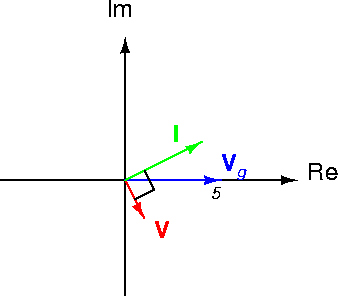
in agreement with (42). The phasor diagram for this problem is shown in Figure 38.


Figure 38: RC phasor diagram.
\begin{figure}
\begin{center}
\epsfig{file=images/acimg6.eps}\end{center}\end{figure}


next up previous contents index

[ENGN2211 Home]

ANU Engineering - ENGN2211