next up previous contents index

[ENGN2211 Home]

Example

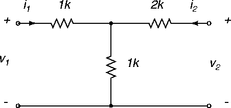
Let's find the impedance and hybrid parameter equivalent circuits of the circuit shown in Figure 58.


Figure 58: Example circuit.
\begin{figure}
\begin{center}
\epsfig{file=images/tpnimg5.eps}\end{center}\end{figure}

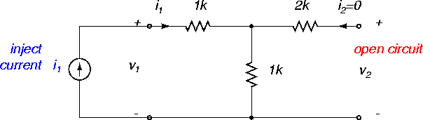
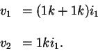
Impedance. Inspection of (67) indicates that we can find z11 and z21 by open-circuiting the right port (i2=0), and injecting a current i1 in the left port and determining the two voltages, Figure 59.


Figure 59: Example circuit with experiment for determining z11 and z21.
\begin{figure}
\begin{center}
\epsfig{file=images/tpnimg6.eps}\end{center}\end{figure}

In this experiment there will be no voltage drop across the 2 k$\Omega$ resistor, and the current i1 flows through both 1 k$\Omega$ resistors. Equation (67) says that

\begin{displaymath}\begin{array}{rl}
v_1 & = z_{11}i_1 ,
\\ \\
v_2 & = z_{21} i_1 .
\end{array}\end{displaymath}

The circuit of Figure 59 says that

\begin{displaymath}\begin{array}{rl}
v_1 & = (1k+1k) i_1
\\ \\
v_2 & = 1k i_1 .
\end{array}\end{displaymath}

Therefore we get

\begin{displaymath}z_{11} = 2 \ k\Omega, \ \
z_{21} = 1 \ k\Omega .
\end{displaymath}

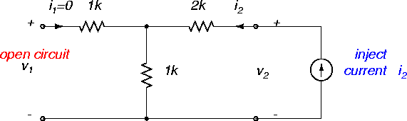
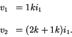
To find z12 and z22 we need a second experiment, Figure 60.


Figure 60: Example circuit with experiment for determining z12 and z22.
\begin{figure}
\begin{center}
\epsfig{file=images/tpnimg7.eps}\end{center}\end{figure}

Equation (67) says that

\begin{displaymath}\begin{array}{rl}
v_1 & = z_{12}i_2 ,
\\ \\
v_2 & = z_{22} i_2 .
\end{array}\end{displaymath}

The circuit of Figure 60 says that

\begin{displaymath}\begin{array}{rl}
v_1 & = 1k i_1
\\ \\
v_2 & = (2k + 1k) i_1 .
\end{array}\end{displaymath}

Therefore we get

\begin{displaymath}z_{12} = 1 \ k\Omega, \ \
z_{22} = 3k \ \Omega .
\end{displaymath}

Now that the impedance parameters have been found, you can draw the impedance parameter equivalent circuit model (exercise).

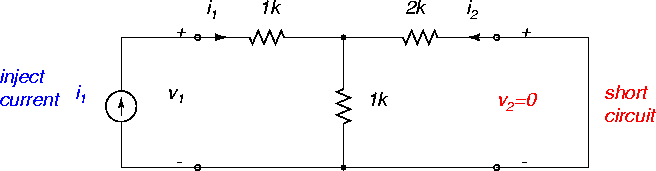
Hybrid. Inspection of (68) indicates that we can find h11 and h21 by short circuiting the right port, injecting a current i1 in the left port and determining v1 and i2, Figure 61.


Figure 61: Example circuit with experiment for determining h11 and h21.
\begin{figure}
\begin{center}
\epsfig{file=images/tpnimg8.eps}\end{center}\end{figure}

Equation (68) says that

\begin{displaymath}\begin{array}{rl}
v_1 & = h_{11}i_1 ,
\\ \\
i_2 & = h_{21} i_1 .
\end{array}\end{displaymath}

From 61, we have

\begin{displaymath}v_1 = (1k + 1k \parallel 2k) i_1 ,
\end{displaymath}

and also by current division

\begin{displaymath}-i_2 = \frac{1k}{1k+2k} i_1 .
\end{displaymath}

Therefore

\begin{displaymath}h_{11} = \frac{5}{3} \ k\Omega, \ \
h_{21} = -\frac{1}{3} .
\end{displaymath}

Exercise. Show that h12 = 1/3, $h_{22} = 1/3 \times 10^{-3}$ $\Omega^{-1}$ and draw the hybrid parameter equivalent circuit. Hint. Open circuit the left port and apply a voltage v2 to the right port.


next up previous contents index

[ENGN2211 Home]

ANU Engineering - ENGN2211