next up previous contents index

[ENGN2211 Home]

Transfer Functions


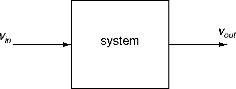
Consider the block diagram illustrated in Figure 44, showing an input voltage vin, and an output voltage vout. The block respresents a system, whose details we leave aside for the moment. The system could be a circuit, or a mechanical system, or... By the way, there is nothing special about voltages here, we could consider currents too.


Figure 44: Block diagram.
\begin{figure}
\begin{center}
\epsfig{file=images/frimg1.eps}\end{center}\end{figure}

The system performs some operation on the input to produce the output. For example, the system could be an amplifier, in which case the output is ideally an amplified copy of the input. An input-output model H is a mathematical operator or function which describes the behaviour of the system:

 
vout = H [ vin ] (53)

So if you want to determine the output for a given input, then calculate (or simulate) using equation (53).

An important type of input-output model for linear systems is the transfer function H(s). Here, s is the complex frequency used in the Laplace transform. We write (53) in the more explicit form

 
Vout(s) = H(s) Vin(s) , (54)

where Vin(s) and Vout(s) are s-domain voltages. We can use a transfer function H(s) as a model for the system as follows:
1.
Given an input vin(t), find $V_{in}(s) = {\cal L}[v_{in}(t)]$.
2.
Multiply Vin(s) and H(s) as in (54) and get Vout(s).
3.
Find the output via $v_{out}(t) = {\cal L}^{-1}[V_{out}(s)]$.

In practice H(s) is found by calculating the ratio

 \begin{displaymath}H(s) = \frac{V_{out}(s)}{ V_{in}(s)} .
\end{displaymath} (55)

When the system is an electric circuit, this is done using standard s-domain circuit calculations. Zero initial conditions are assumed.

Consider the RC circuit of Figure 25, with R=1 $\Omega$, C=0.5 F, and vC(0-)=0 V. Let vin=vg, and vout=vC. The s-domain circuit is shown in Figure 45.


Figure 45: RC circuit in s-domain for transfer function calculation.
\begin{figure}
\begin{center}
\epsfig{file=images/frimg2.eps}\end{center}\end{figure}

By voltage division we have

\begin{displaymath}V_{out}(s) = \frac{ \frac{2}{s} }{ \frac{2}{s} +1} V_{in}(s) ,
\end{displaymath}

so that

\begin{displaymath}\frac{ V_{out}(s)}{V_{in}(s) }
= \frac{ \frac{2}{s} }{ \frac{2}{s} +1}
= \frac{2}{s+2} .
\end{displaymath}

Therefore the transfer function relating input (source) voltage to output (capacitor) voltage is

 \begin{displaymath}H(s) = \frac{2}{s+2} .
\end{displaymath} (56)

Notice that the transfer function is a rational function of the complex frequency s. In general it has the form

 \begin{displaymath}H(s) = \frac{b(s)}{a(s)} ,
\end{displaymath} (57)

where a(s) and b(s) are polynomials (of degree n and m respectively).

The equation

 
a(s) = 0 (58)

is called the characteristic equation.   The roots $p_1,\ldots,p_n$ of the characteristic equation are called poles,  and they determine the nature of the response, as illustrated in Figure 46.


Figure 46: Complex frequency. (From Johnson, Hilburn, Johnson and Scott.)
\begin{figure}
\begin{center}
\epsfig{file=images/comps.eps} %
\end{center}\end{figure}

The roots $z_1,\ldots,z_m$ of the equation

b(s)=0

are called zeros.  


next up previous contents index

[ENGN2211 Home]

ANU Engineering - ENGN2211