 |
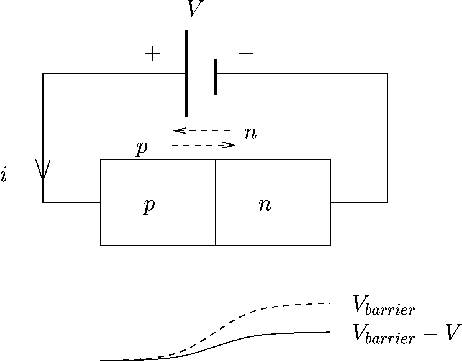
When a positive voltage is applied to the anode (p side) relative to the cathode (n side), the junction is said to be forward biased, see Figure 70.
The effective barrier potential is reduced by the applied voltage, and majority carriers can flow across the junction. This results in a large current flow. The junction is switched on.
When a negative voltage is applied to the p side (anode) relative to the n (cathode), the junction is said to be reverse biased, see Figure 71. The effective barrier potential is increased by the applied voltage, and only a small minority carrier current flows. To a first approximation this reverse current is zero - the junction is switched off.
ANU Engineering - ENGN2211