PSPICE has a feature which allows you to automatically change a part value within a specified range and to simulate and graph the results. This is called DC sweep. For instance, resistor values, currents, or voltages can be swept.
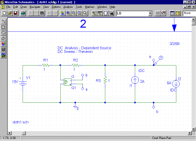
As an example of this, suppose we want to experimentally determine the Thevenin equivalent of the circuit of Figure 9 to the left of the terminals a-b. This can be done by injecting a current and recording the voltage for each current value. PSPICE can do this automatically by using its DC sweep feature applied to the current source I2 of Figure 11.
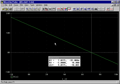
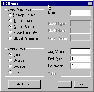
Load the PSPICE file dcth1.sch corresponding to Figure 11. The DC sweep should be set up to vary I2 over the range -2-10 A with increments of 0.1 A (if not, see below). Simulate the circuit and obtain the graph shown in Figure 12.
Using Probe. The graph is displayed in the PROBE window. PROBE has its own menus for a wide range uses in examining the output from a PSPICE simulation. In the example, the current source I2 ranges over the horizontal axis, and the voltage Vab (i.e. V(a)) is on the vertical axis. Figure 12 shows the use of the cursor, which is activated by:
ToolsThere are two cursors controlled by the left and right mouse buttons, respectively. The small Probe Cursor window shows the measurements for the current cursor positions, including the difference.Cursor
Exercise. From your PSPICE graph, determine:
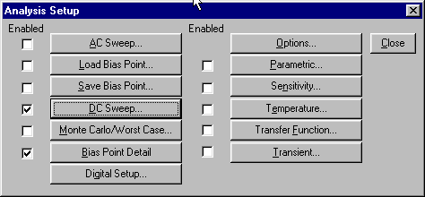
Setting up DC sweep. In order to carry out the simulation you want, you have to tell PSPICE your requirements. The DC operating point analysis is done by default. For DC sweep, you need to set up as follows.
AnalysisThe Analysis Setup dialog box, Figure 13 will appear.
ANU Engineering - ENGN2211