With a complete schematic in the project, you can do a functional simulation of the digital circuit. This allows you to check the basic operation of the circuit so you can debug it before implementing it in hardware. This does not take into account lower level details.
Open the Logic Simulator by clicking on the Simulation icon in the main window.
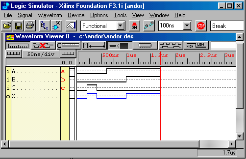
In the Logic Simulator window, open the existing simulation state:
Fileand select andor.des. You should see the waveform of Figure 9.Load Simulation State...
The simulator uses a netlist generated from the schematic file. The existence of such a netlist is indicated by a tick (check) in the Design Entry icon. Netlists are also used for implementation. It is not hard to reset the simulation waveform - figure out how to do this and do it.
ANU Engineering - ENGN3213