

[ENGN2211 Home]
In many cases, it suffices to use the practical model of the diode,
Section 7.2.3.
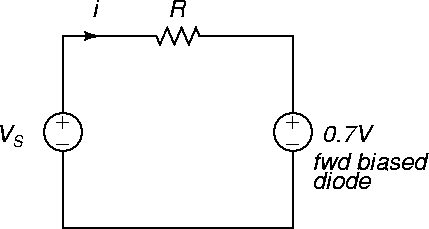
The circuit of Figure 77 can be redrawn as follows,
Figure 79:
Figure 79:
Diode biasing circuit showing practical model.
 |
So v=VQ=0.7 V since the diode is always forward biased in this circuit, and
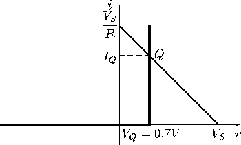
Therefore the practical model gives i=IQ=4.3 mA, as shown in Figure 80.
Of course, it is very easy to determine the operating point from this diagram.
Figure 80:
Resistor-diode circuit analysis showing practical diode characteristic and load line.
 |


[ENGN2211 Home]
ANU Engineering - ENGN2211
