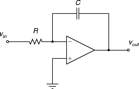
A circuit diagram of an opamp in a integrator configuration is shown in Figure 17.
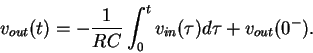
The basic input-output relationship for the integrator
circuit is
Exercise. Derive formula (15). Hint: Make use of Ohm's law for capacitors to work out the capacitor current, equation (17).
PSPICE file:
inta1.sch.
(For practical reasons, a 50 M![]() resistor
is included in series with the capacitor.)
resistor
is included in series with the capacitor.)
ANU Engineering - ENGN2211