next up previous contents index

[ENGN2211 Home]

Adder

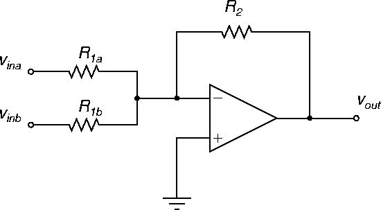
  A circuit diagram of an opamp in a adder configuration is shown in Figure 16.


Figure 16: Adder or summing amplifier.
\begin{figure}
\begin{center}
\epsfig{file=images/opampimg4.eps}\end{center}\end{figure}

This circuit has two inputs, and the basic input-output relation is

 \begin{displaymath}v_{out} = -\frac{R_2}{R_{1a}} v_{ina} -\frac{R_2}{R_{1b}} v_{inb} .
\end{displaymath} (15)

Exercise. Derive formula (15). Hint: It is similar to the inverting amplifier.

PSPICE file: suma1.sch.


ANU Engineering - ENGN2211