Any two conducting objects in space have a capacitance between them. What this means phyically is that if these objects differ in potential, electric field lines emanating from one object and terminating at the other lead to an accumulation of equal and opposite charge on the objects. Similarly, removing charge from one object and placing it on the other leads to a difference in potential. This charge accumulation leads to a flow of current in an external circuit connecting these objects should the potential be made to vary. (see also the discussion in lectures) .
It is possible to talk about the capacitance of an object with respect to infinity. This can be a useful idea when trying to assess the object as a candidate for RF earth. The criterion is the degree to which the object can comsume charge without changing its potential. Of course this implies simply that the object has to be 'big' in some sense. The larger its radius then the lower is its potential with respect to infinity for a given charge that it contains on its surface What laws of electromagnetism are being used here?. The corollary of this is simply that an earth plane by and large has to be bigger than the components in the circuit competing for its charge. Dont forget however that ability to absorb charge is one thing. The other property of a good RF earth is that the potential difference caused by currents flowing in it must be much lower than the differences in potential in the external circuit.
The capacitor circuit component consists of a conducting plate separated by a dielectric. A dielectric is an insulator. The simplest dielectrics are air or vacuum and these provide the most efficient dielectrics. Although air gap or vacuum capacitors exist especially for high power applications, they obviously rely on bulky structures to provide mechanical separation for the plates. Most small component type caps for electronics therefore consist of a pair of metal foils separated by a dielectric material. The dielectric material may also have a large dielectric constant which helps to increase the capacitance per unit size of the capacitor.
When an electric field penetrates a dielectric, the electron clouds in atoms are displaced. This leads to a net negative charge on the surface of the dielectric facing the imposed external electric field and a positive charge on the other.
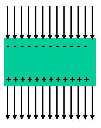
The electric field inside the dielectric is related to the electric field outside the dielectric by Eext = &epsilon r Ed and hence the charge per unit area on the surface of the dielectric by
&sigmad = - &epsilon0( &epsilonr - 1)Ed.where &epsilon0 is the free-space permittivity = 8.85 x 10⁻¹² Farads/meter and &epsilonr is the relative permittivity or dielectric constant (eg 1 for air and vacuum, 6 for lead glass) . Note that the subscript "r" in &epsilonr means "relative" and not "real part". &epsilonr is in fact a complex number. Since the dielectric constant is normally greater than unity, the electric field in the dielectric is less than the external field. The following figure shows a capacitor in a circuit with an applied oscillating voltage.
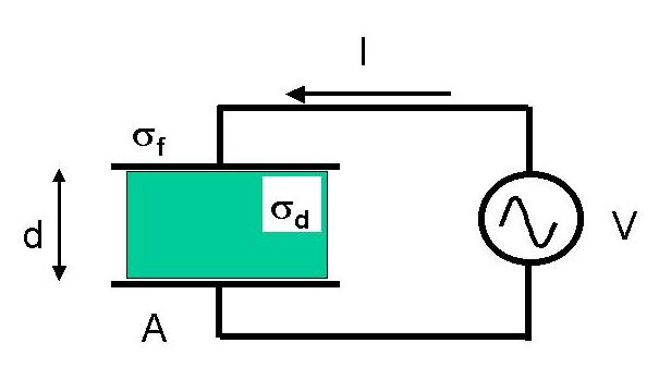
The dielectric is sandwiched between two metal plates connected to the voltage source. Under these conditions the external electric field is sandwiched in between the dielectric and the plates and is zero outside the capacitor. Inside the dielectric there is also an electric field. The charge per unit area on the surface of the capacitor is given by
&sigmad = -&epsilon0(&epsilon r - 1)Edbut now there is also free charge (&sigmaf) accumulating on the plates. If we apply Gauss's law directly using the electric field within the dielectric we obtain,
&sigmaf + &sigmad = &epsilon0Ed.
Note that the free and bound charges are opposite in sign. Therefore
&sigmaf = &epsilon0 &epsilonrEd = &epsilon 0Eext = D,the electric displacement. Since the voltage is related to the electric field by V = Edd, the capacitance is given by,
C = &sigmafA/V = &epsilon0&epsilon rA/d.where Q = &sigmafA is the charge on the plates and A is the surface area of the plates. Since the relative dielectric constant can lie in the range 1 - 10000, it is clear that dielectrics can be used to reduce A significantly and hence the size of the capacitor.
The unit of capacitance is the Farad. One Farad corresponds to 1 Coulomb of charge being stored on the plates at a potential difference of one volt. This amount of charge is mighty big. Normal "hand-held" values of capacitance range from 0.1 pF to milliFarads. Values of capacitance < 1pF are easily produced by stray effects in circuits. Charging an 850 &mu F capacitor to 400 Volts and discharging it with a screw driver will go off with a mighty bang. (Energy in the spark = 1/2CV2 = 68 Joules, and 400 Volts is lethal, so if you contemplate trying this trick out remember that practice makes perfect).
In this course where radio circuits in the range of 10 MHz to 1 GHz are studied, the capacitances that you will typically use are in the range of .1 pF - 1 nF. Larger values such as 1 nF - 10 &mu F would be used for inter-amplifier stage coupling and power supply decoupling.
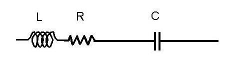
Dielectrics get lossy when the electric field oscillates and the connecting leads have inductance. As a result the equivalent circuit of a capacitor often looks like the following.
A useful concept that is of concern in high Q applications is the loss tangent. The loss tangent, tan&delta of a dielectric is the ratio of the imaginary to the real parts of &epsilonr.
tan(&delta) = Im[&epsilon r] / Re[&epsilon r].A related quantity is the power factor of the dielectric which is the ratio of the imaginary part of &epsilon r to its magnitude.
The refractive index, n, is related directly to the relative dielectric constant by,
n = &epsilon r1/2.The most common applications of capacitors at RF are to block DC and transmit RF or to bypass DC power lines so that they do not carry RF current. In this case the bypass capacitor becomes the defacto power supply for the RF circuit and is used to eliminate unwanted stray inductance arising from wiring or PCB tracks from appearing in circuit. Depending on the situation, this could imply the use of a large value surface mount ceramic capacitor soldered right on the emitter of a transistor in a common emitter RF amplfier.
Precise and stable capacitors are required in resonant circuits where variations in the capacitance bare directly on the frequency of operation. However the most common applications here are in low Q filters and matching networks where the stability requirements are not super-critical. For frequency references of extremely low phase noise oven (temperature) controlled crystal oscillators (OCXO / TCXO's) are employed. As may be obvious from the workin this course, accurately tuned LC tank circuits are a thing of the past. All precisely tuned frequency generators rely on crystal locked circuits such as Phase Lock Loops.
Ceramic capacitors are a cheap and small sized choice for the bypass application. These can have very large values of &epsilonr and hence small size, but can be very unstable with temperature ( up to 105 ppm/oC). Tantalum capacitors are a good low inductance choice for RF applications. These are polar which means that they must have a fixed DC voltage of the right polarity across them or otherwise they will be destroyed (usually in spectacular ways). In radio frequency circuits, tantalum capacitors are typcally used together with a lower value ceramic capacitor to achieve bypassing over both low and high frequencies.
For very stable applications (20 ppm/oC) requiring low loss there are silvered mica capacitors. In all cases, take special note of their voltage ratings.
There are also various kinds of vacuum or air variable capacitors. For HF-VHF applications the multi-plate and vacuum variable caps come in all sizes and can provide up to several factors of ten in range. Unfortunately they come with only one price tag nowadays. Common values may be from 1-15 pF, 20 - 300 pF or even 100 pF - 1nF. These kinds of tunable capacitors used to be employed as the tuners in valve radios from the 1950's. Nowadays they are only good for high power applications such as antenna matching or tuning networks where some degree of tuning is unavoidable and the job cannot be done at low power. Some examples of this are tuning networks for matching high power transmitters (hundreds of Watts to hundreds of MWatts) to magnetic loop antennas used for plasma formation and heating. Such RF discharges are used in thermonuclear fusion and industrial plasma experiments. Another example is power tuning networks used to couple low frequency linear amplifiers to either broadband or electrically short antennas. This application is common in amateur radio where broadband antenna systems are preferred if possible or often the low frequencies (HF) make electrically short antennas unavoidable.
This describes the rare case of high power tunability. Usually amplifiers driving antennas in telecommnications drive the antenna at its resonant frequency where its impedance is already matched. Thus the only requirement of tunability is in the local oscillator itself. For this purpose the basic device is the voltage variable capacitor or Varactor diode.
For applications at frequencies > 100 MHz, surface mount capacitors with flat ribbon leads are a better option with low internal inductance.
RC FILTERS
Now that we have looked at resistors and capacitors at RF, we are ready to investigate the design of a simple passive filter.. the RC filter. RC filters are not used very extensively at RF because they do not provide significant out-of-band attenuation. This makes them virtually useless for any RF application requiring the separation of two RF frequencies. Often however one wants to separate audio frequency signals from RF, either to filter out the audio (high pass filter) or to recover the audio from RF or RFI (low pass filter). They are also used to separate the baseband signal at the output of a mixer after IQ demodulation. Coupling capacitors used in amplifiers to separate DC from the RF are a trivial case of RC filters where the capacitor plays the role of a DC block.
THE LOW PASS FILTER
The impedance of a capacitor decreases (most of the time!) with frequency whereas the impedance of a resistor stays constant. The following circuit therefore attenuates high frequencies by voltage divider action. It is a low pass filter.
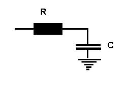
For this circuit to function correctly, the capacitor cannot be "loaded" by the impedance of whatever circuit takes the low frequency output. Normally this is not a problem because there is no requirement to terminate an audio signal in a low value "characterstic" impedance as there is at RF.
The most common situation is that the low pass filter will be fed by a source of modest output impedance usually a characteristic impedance of about fifty Ohms and the output will go to a low frequency processing circuit such as an audio buffer or oscilloscope with over 1 M&Omega of input impedance. In this case an R of about 10k&Omega will neither load the source nor be loaded by the circuit connected to its output. Usually however one should then terminate the RF signal feeding the low pass filter by placing a resistor of value equal to the charactristic impedance of the source from the input of the 10k&Omega resistor to ground. The frequency at which the input signal is attenuated to -3 dB (the cutoff frequency) is then given by 1/(2&pi RC) and can be chosen by the value of C. Such a low pass filter attenuates at a rate of 20 dB per frequency decade above the cutoff frequency. This is not such a great rate of attenuation but is enough when there is such a large difference in frequencies as occurs between radio and audio frequencies.
Higher rates of attenuation can be achieved by cascading such filters. The simplest way to do this is to cascade a set of stages with ever increasing values of R. If the values of successive R's are at least 3 times larger than the previous value then, for an N stage filter, the attenuation in the stop band would be 20N dB per decade, with minimal effect on the in-band characteristics. Note however that, assuming all stages have the same RC (time constant) value, then the 3 dB cutoff frequency is now given approximately by 1/(2&pi NRC).
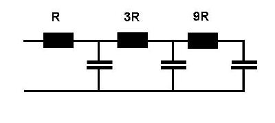
Even though the values of R increase from the lowest value from input to output, the input and output impedances in the pass band are equal to the sum of all the resistors. The problem with such cascaded filters is that the transition from the pass to the stop band is always relatively soft. As a result, this is not the way to make a filter with a steep roll off. To do so requires the implementation of filters made of both capacitors and inductors or their equivalent. There are numerous resouces in both text form and software describing these filters and their implementation (e.g. Bowick).
Ex. 4. Given that the (phase) velocity of an electromagnetic wave in an infinite dielectric is related to the speed of light in vacuo by v = c/n, what is the effect of finite loss tangent on the propagation of the wave?
Ex. 5. Derive an expression for the loss tangent from the equivalent circuit of a capacitor.
Ex. 6. Using MATLAB investigate the effects of the stray L (~10 nH) and R (~1&Omega) for several capacitor values with the above equivalent circuit over the frequency range 1 MHz - 1 GHz. Describe all the features that you observe in the impedance plots. What range of capacitance values are most resistance to these L and R strays. ( HINT: Sample matlab program )