A varactor diode is a diodes is reverse bias capacitance can be varied by changing the reverese bias voltage. A diode is simply a PN junction. When reversed biased a positive voltage is applied to cathode and negative voltage is applied to the anode.
When a reverse voltage is applid to a PN junction, the holes in the p-region are attracted to the anode terminal and electrons in the n-region are attracted to the cathode terminal creating a region where there is little current. This region, the depletion region, is essentially devoid of carriers and behaves as the dielectric of a capacitor.
The depletion region increases as reverse voltage across it increases; and since capacitance varies inversely as dielectic thickness, the junction capacitance will decrease as the voltage across the PN junction increases. So by varying the reverse voltage across a PN junction the junction capacitance can be varied .This is shown in the typical varactor voltage-capacitance curve below.
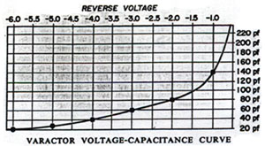
Notice the nonlinear increase in capacitance as the reverse voltage is decreased. This nonlinearity allows the varactor to be used also as a harmonic generator.
The obvious varactor diode considerations are:
(a) Capacitance value
(b) Voltage
(c) Variation in capacitance with voltage.
(d) Maximum working voltage
(e) Leakage current
However an often overriding consideration in the design of an RF oscillator (where varactors are most useful) is to make sure that they do not compromise the tank circuit Q too much. Otherwise the varactor diode may cause the oscillator to cease oscillating.
The datasheets for the BB833 varactor diode used in the project are here