 |
The state diagram and next state/output table for the vending machine controller were given earlier in Section 4.4.
A common, simple, though not minimal binary coding of states is called one hot, where one flip flip is used for each state. One hot coding is suitable for the FPGA architecture, which is rich in flip-flops. (You may have noticed the one hot option in the Xilinx compilation options). In this example we have six states, and with one hot coding we use six flip flops (a minimal binary coding would require three flip flops).
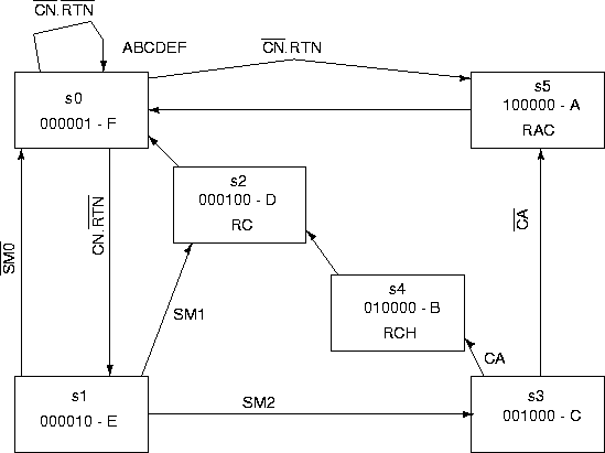
Using state variables ABCDEF the one hot coding is as follows:
| state | ABCDEF |
| s0 | 000001 |
| s1 | 000010 |
| s2 | 000100 |
| s3 | 001000 |
| s4 | 010000 |
| s5 | 100000 |
We use a similar coding for the inputs and outputs, (although there are many valid possibilities) with the followng abbreviations:
| input | abbreviation | output | abbreviation |
| coin | CN | release-candy | RC |
| return | RTN | return-change | RCH |
| sum<75 | SM0 | return-all-coins | RAC |
| sum=75 | SM1 | ||
| sum>75 | SM2 | ||
| change-available | CA |
With this coding, the next state/output tables read:
| Present | next | next | next |
| state | state | state | state |
| ABCDEF | |||
| 000001 | 000001 if CN=0 | 000010 if CN=1 | 100000 if CN=0 |
| and RTN=0 | and RTN=0 | and RTN=1 | |
| 000010 | 000001 if SM0=1 | 000100 if SM1=1 | 001000 if SM2=1 |
| 000100 | 000001 | - | - |
| 001000 | 010000 if CA=1 | 100000 if CA=0 | - |
| 010000 | 000100 | - | - |
| 100000 | 000001 | - | - |
| Present state | RC | RCH | RAC |
| ABCDEF | 0 | 0 | 0 |
| 000001 | 0 | 0 | 0 |
| 000010 | 0 | 0 | 0 |
| 000100 | 1 | 0 | 0 |
| 001000 | 0 | 0 | 0 |
| 010000 | 0 | 0 | 1 |
| 100000 | 0 | 1 | 0 |
The state diagram can also be re-drawn as in Figure 71. This may help you see what the coding means (do this yourself for the up/down/stop counter).
As we can see, each state is associated with exactly one flip flop. The vending machine circuit diagram is shown in Figure 72.
We again use rising edge triggered D flip flops as shown,
with asynchronous preset and preclear.
Activation of the RESET signal will force the state machine
into state s0=000001.
Then it
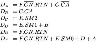
is quite straightforward to obtain the next state logic:

The output logic is also straightforward to obtain:

ANU Engineering - ENGN3213