 |
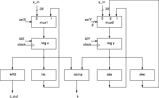
A data subsystem for the incdec example is shown in Figure 91.
This data subsystem consists of a number of functional modules together with input, output and control signals. These facilitate the actions in the algorithm.
The data subsystem is controlled by the following control points:
| ldX | load register x |
| ldY | load register y |
| selX | select input to x (1 bit) |
| selY | select input to y (2 bit) |
The data subsystem provides the following condition for the control subsystem:
| k | k=1 if x < y; zero otherwise |
| start | external signal to start execution |
The modules used in the data subsystem may come from a standard parts library, or designed specifically.
ANU Engineering - ENGN3213