| RS (run/stop) | MODE | Operation |
| 0 | HOLD | |
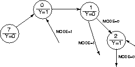
| 1 | 0 | binary count |
| 0,1,2,3,4,5,6,7,0,... | ||
| 1 | 1 | Gray count |
| 0,1,3,2,6,7,5,4,0,... |
| output | function | display device |
| LED[2:0] | binary code for current count value | 7-segment display |
| Y=0 | odd count value | LED |
| Y=1 | even count value | `` |
| Xilinx | Xilinx board | Trainer board | |
| signal | pin | resource | resource |
| MODE | P19 | SW3-1 | - |
| RS | P20 | SW3-2 | - |
| Y | P60 | LED-1 | - |
| CLOCK | P13 | - | TTL clock |
| LED<0> | P10 | - | 7-seg A |
| LED<1> | P9 | - | 7-seg B |
| LED<2> | P8 | - | 7-seg C |
ANU Engineering - ENGN3213