

[ENGN3213 Home]
The VHDL structural description of the pedx controller was at a rather low level,
specifying an explicit description in terms of JK flip flops.
In VHDL we can describe sequential circuits more abstractly,
and let the compiler take care of the details of implementation.
In this course we will be using the State Editor to create
VHDL source code for our state machine designs. There are a number
of reasons for this, including:
- 1.
- It is conceptually important and useful to think in terms of
state diagrams when designing state machines. (Recall that the State Editor
provides a graphical tool to create state diagrams.)
- 2.
- It can be difficult to use VHDL for synthesis, since because
of the language's power and flexibility it is easy to create code that cannot be
synthesized by current VHDL synthesis tools.
The State Editor produces code that can the synthesized.
You will now create the pedx controller directly from the
state diagram of Figure 31
(the state numbering may be offset by 1).
- 1.
- Create a new Xilinx VHDL project pedxv2 for the pedx controller.
- 2.
- Start the State Editor, and enter the state diagram of Figure 31:
- (a)
- To add a new state
FSM  State
State
- (b)
- To add a new transition
FSM  Transition
- (c)
- To add a new condition (for a transition)
FSM  Condition
- (d)
- To add a new output (for a state)
FSM  Actions
  State
State
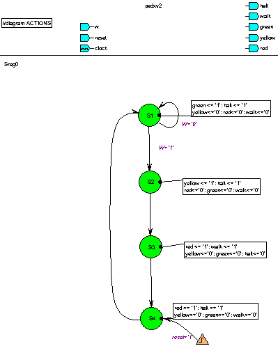
Your state diagram should appear as in Figure 39.
- 3.
- Create the VHDL code from the state diagram. Then open the VHDL file and check the
syntax. Correct any errors.
- 4.
- Add the VHDL file to the project, and synthesize your design.
- 5.
- Simulate your design, and check for correct operation.
- 6.
- Implement your design.
Figure 39:
State diagram for the pedestrian crossing traffic light controller
in the State Editor.
 |


[ENGN3213 Home]
ANU Engineering - ENGN3213
 State
State
 Transition
 Condition
 Actions
  State
State
State
Transition
Condition
Actions
State