Software Design
This plan structures and organizes
the software modules, including on-board control, off-board guidance, and
intermediate interfaces, to create an architecture enabling supervised
autonomy for an underwater robotic vehicle.
1.0 Objectives
The objective of this research
is investigate underwater robotic autonomy. The software system is expected
to:
· Enable an autonomous
underwater vehicle to: observe the surrounding dynamic features, follow
along static features, swim after dynamic targets, and search in a regular
pattern.
· Investigate control
techniques applicable to underwater robotic control and evaluate traditional
feedback control as well as reactive, behavior-based, and neural-based
methods.
· Develop visually-based
control techniques
· Develop an approach
to control of an underwater robot that combines fundamental reflexes with
guidance by deliberative planning.
2.0 Approach
The sensing, planning, and control
tasks that Kambara must perform are decomposed into computational processes.
Each performs as independently as possible but the overall action of the
robot depends on and is emergent from inter-process interaction. Within
this decentralized model, processes consume and transform sensory input
data and determine and produce output actions consistent with the robot's
objectives.
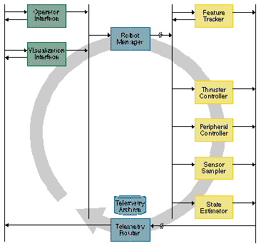
3.0 Architecture Design
The software architecture details
the overall structure and collective behavior of the software system. The
software modules are designed as independent computational processes that
communicate as shown in Figure
3-1. The Robot Manager is the downstream communication module, directing
commands to the modules running on-board. The Feature
Tracker uses visual sensing to follow targets in the environment and
uses the relative motion to guide the Robot Neurocontroller or to generate
control signals directly. The Robot
Controller (Robot Neurocontroller) interprets position-based goals
to produce control signals for the Thruster Controller. The Thruster
Controller runs stable closed-loop servo control over all the robot's
motions. The Peripheral
Controller drives all other devices on the robot, for example cameras
or scientific instruments. The Sensor
Sampler collects sensor information and updates the controllers and
the State Estimator.
The State Estimator
interprets sensor information to generate estimates, to dead reckon position,
and passes raw and estimated state information off-board to the Telemetry
Router. The Telemetry
Router moves robot state and acquired image and science data upstream
to any number of public consumers and a telemetry archives.
|
The Visualization
Interface transforms robot telemetry into a description of robot state
that can be rendered in a three-dimensional view. The Operator
Interface interprets telemetry and presents a numerical expression
of robot state. It provides method for generating commands to the Robot
Manager for direct teleoperation of robot motion and for supervisory control
of the on-board modules. The Operator
Interface can operate in conjunction with the Visualization Interface
to preview robot actions.
The Path
Planner interprets robot telemetry to analyze performance and adjust
behavior accordingly, for example adjusting velocity profiles to better
track a pattern. A Terrain
Mapper could interpret terrain data (like images from peripheral sensors)
into maps that can be rendered by the Visualization
Interface or used by the Path
Planner to modify walking behavior in anticipation of changes in the
terrain. The Mission
Planner plans sequences of Path changes for the Path
Planner to produce complex trajectories for the robot. If terrain maps
are available the Mission Planner can autonomously navigate the vehicle
to goal locations.
The telemetry stream, images,
and science instrument data is archived by various modules using a common
referencing and synchronization scheme.
3.1 Operational Modes
The software architecture is
designed to accommodate a spectrum of operational modes. Direct teleoperation
of the robot with commands fed from the operator straight through to the
controllers provides the most explicit control of robot action. While invaluable
for development, this mode is not practical for long-delay telemetry conditions.
Supervisory teleoperation, in which compound commands are sequenced off-board
and then interpreted over time by the modules on-board, is the most common
operational mode. Further along, large portions of the robots operation
can be generated on-board as it essentially becomes an autonomous robot.
Planners running off-board and on-board interpret the operator's infrequent
guidance into sustained operation.
3.1.1 Direct Teleoperation
Under direct teleoperation,
operator commands, in the form of single control commands interpretable
by the
Thruster Controller
or
Peripheral Controller
are forwarded on-board by the Robot Manager. The
Interfaces
collects raw state information and transmits it off-board for the operator
to view in the
Operator
Interface and
Visualization
Interface. This simplified architecture appears in
Figure
3-2.
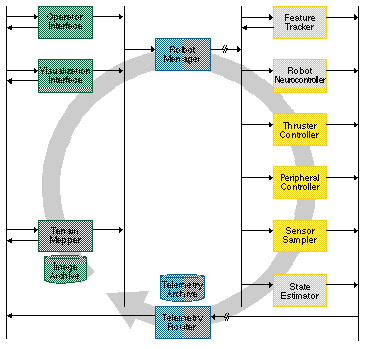
3.1.2 Supervisory Teleoperation
Under supervisory teleoperation,
the operator's commands are infrequent and provide guidance that is abstracted
away from direct action commands. The operator gives guidance equivalent
to "swim to that feature" and "remain on station" (but not in natural language)
which the
RobotManager
forwards primarily to the on-board Robot Neurocontroller. The
Robot
Controller (Robot Neurocontroller) decomposes the plans into parameters
that describe the robot behavior. The
State
Estimator aids in this operation by monitoring robot state and computing
relevant estimates, like the position in the world. This state information
is forwarded by
Telemetry
Router to the Visualization Interface and converted to form that can
be used to render the current state of the robot. The
Visualization
Interface also interacts with the
Operator
Interface to enable the operator to preview potential commands. A
Terrain
Mapper could collect visual images from the telemetry stream and constructs
elevation maps of the terrain, registered to a common coordinate system.
These maps can be rendered in a virtual environment or displayed to the
operator in various formats. This form of the architecture appears in
Figure
3-3.
|
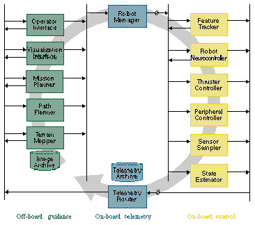
3.1.3 Autonomous Operation
Under autonomous operation,
the operator is removed from the primary control cycle. A
Path
Planner and
Mission
Planner (or group of planners), monitors telemetry to obtain state
information and interact with a Terrain Mapper to generate command sequences
for the robot. The planners may be guiding the robot over a long traverse,
moving from one target to another, or thoroughly exploring a science site.
The complete architecture appeared in
Figure
3-1.
4.0 Functional Design of On-board Modules
4.1 Telemetry Router
4.1.1 Introduction
The Telemetry Router (tr) sends
data at 5Hz upstream where it is logged and distributed. The telemetry
is provided by on-board modules which access a shared data structure. Each
periodic telemetry message is 347 bytes, as follows:
Some telemetry occurs aperiodically
in individual large messages:
4.1.2 Inputs
Telemetry data is input to
the Telemetry Router by methods which store values into the telemetry data
structure.
The Telemetry Router also requires
specification of its output rate and the channel along which it will send
data.
4.1.3 Processing
The function of the Telemetry
Router is to regularly send state information from its internal data structure
through an established communication channel to a single off-board module.
The Telemetry Router must open
the communication channel, likely a socket connection using the UDP protocol,
and write a stream of data to the channel.
The Telemetry Router need not
perform any handshaking or data checking/correcting.
4.1.4 Outputs
The Telemetry Router must stream
state information at regular intervals. Additional information including
digitized images and error signals may be produced at irregular intervals.
4.1.5 Interfaces
|
|
|
Send state information with
timestamp and (positions, velocities, alterations, forces, torques, power,
and condition flags; inclinometer values; roll/pitch values; and condition
flags) |
|
|
(int id, struct state, struct
data...) |
Send a portion of an image
with state |
|
|
(int code, int datasize,
int data...) |
Signal an error condition |
4.1.6 Performance
The Telemetry Router's nominal
telemetry rate is 5Hz.
4.2 RobotManager
4.2.1 Introduction
The Robot Manager (rm) runs
onboard the robot and receives commands from the Operator Interface and
relays them to the appropriate onboard module. It maintains security by
insuring that only one trusted operator interface can command the robot.
4.2.2 Inputs
The input is a command from
an Operator Interface as defined in the
4.2.5.
4.2.3 Processing
The Robot Manager receives
commands, likely via a TCP/IP socket, and verifies that the particular
Operator Interface is allowed to issue commands to the robot. If so, the
command is transmitted to the appropriate module.
4.2.4 Outputs
The Robot Manager passes command
parameters to other onboard modules either by signaling or by invoking
a local method.
4.2.5 Interfaces
|
|
|
|
|
|
(int joint)
(int thruster |
Stop motion of specific joint
or thruster |
|
|
(int joint, int position) |
Command a specific joint
to rotate to a relative position |
|
|
(int thruster, int torque) |
Command the torque of a
specific thruster |
|
|
(int device, int parameter,
int value) |
|
|
|
|
Set parameters describing
desired target. |
|
|
float argument,
int numWaypoints,
float x[10],
float y[10]) |
Track waypoint positions
along a path. |
4.3 Feature Tracker
4.3.1 Introduction
The Feature Tracker (ft) will
implement feature and/or texture based correlation algorithms for following
objects in the visual field of the robot. The changing position of these
feature objects may be used by the robot controller to command change in
the vehicle position and orientation or by the peripheral controller to
command change in camera pan-tilt orientation.
4.3.2 Inputs
The Feature Tracker requires
as input either an image of the extracted feature, an interest operator
that extracts the feature, or the position and extent of the feature in
an identified image.
4.3.3 Processing
The Feature Tracker will extract,
transform and store the input feature, called a template. This feature
is then located in the video stream of each camera of the stereo pair.
Motion-based stereo in each stream track the movement of the feature in
image space while position of the feature in the two streams (position-based
stereo) is used to estimate the range to the feature.
The Feature Tracker will likely
need to compensate for the change appearance of templates by filtering
noise, normalizing variations, rectifying image distortion, and maintaining
a collection of templates associated with each tracked feature.
4.3.4 Outputs
The Feature Tracker outputs
the position of the feature in image space and the distance from the camera
coordinate system to the feature.
4.3.5 Interfaces
|
|
(int x, int y, struct parameters) |
Track feature at image coordinate
{x,y} |
|
|
|
Track feature with template |
|
|
|
Identify a feature to track |
4.3.6 Performance
The Feature Tracker must be
capable of estimating the position and range of a target at 10Hz. It is
desired that it be capable of tracking three independent targets at 10Hz.
4.4 Robot Controller
(Robot Neurocontroller)
4.4.1 Introduction
The Robot Controller (currently
designed as a neurocontroller) (rc) provides on-board thruster command
generation and monitoring of vehicle state.
In the case of the Robot Neurocontoller,
it must both generate stable control to move the vehicle, and learn the
proper control signals to achieve the desired motion. Essentially the neurocontroller
must learn an internal model of the vehicle and its control parameters
from its experience in the world.
A conventional Robot Controller
requires a preprogrammed physical model which it uses to control the vehicle
4.4.2 Inputs
The state of the robot as measured
by the Sensor Sampler, estimated by the Thruster Controller, and derived
by the State Estimator. Either information about goal position from the
Robot Manager or about the position of the target feature from the Feature
Tracker sets the desired state.
4.4.3 Processing
The controller determines (at
high frequency) the thruster command vector that will best reduce the "distance"
between the current state and the desired state, This is done by feedback
control of the system using the input
The neurocontroller has at least
two independent tasks, one which produces control commands and another
which processes state and action information to learn how to better produce
control commands.
4.4.4 Outputs
The output of the Robot Controller
is a command to the Thruster Controller indicating the appropriate force
levels for the vehicle's thrusters.
4.4.5 Interfaces
|
|
|
Move to a relative position
(and absolute orientation) |
|
|
struct position[numWapoints]) |
Follow waypoint positions
along a path. |
4.5 Thruster Controller
The Thruster Controller (tc)
runs all on-board servo loops. It obtains setpoints form the Robot Manager
or Robot (Neuro)Controller. It also provides thruster state information
to the Sensor Sampler
The Thruster Controller is implemented
in two parts, one of which runs on the main processor acting as an interface,
the other of which runs on the processor dedicated to the motion control
servos ("the servo loops").
4.5.1 Inputs
The input to the interface
process is a vector of the desired force levels of the vehicle's thrusters.
This processes passes to the servo loops the desired current for the thruster
to consume.
4.5.2 Processing
The interface process must
implement the thruster model in order to convert desired force to an appropriate
current level. The servo loop must vary the PWM signal to the amplifier
to effect the voltage of the amplifers. On the amplifiers a measurement
of the current consumed by the motor is made. The servo loop varies the
PWM signal, changing motor speed, and thereby changing the current consumed.
The current consumed is proportional to thrust produced. The servo loop
relays the voltage and current to the interface process
4.5.3 Outputs
The Thruster Controller outputs
the motor voltage and current and its estimate of thrust forces. This data
is collected by the Telemetry Router for forwarding and used by the Robot
Controller.
4.5.4 Interfaces
|
|
|
|
|
|
(int thruster)
|
Stop motion of specific thruster |
|
|
(int thruster, int velocity) |
Command the velocity of
a specific thruster |
|
|
(int thruster, int torque) |
Command the torque of a
specific truster |
|
|
(int thruster, int parameter,
int value) |
|
4.6 Peripheral Controller
The Peripheral Controller (pc)
initializes the various peripheral devices including imaging devices and
pan/tilt actuators.
The Peripheral Controller initiates
any calibration routines that are required at startup.
The Peripheral Controller is
responsible for monitoring internal leak detectors, signalling any leakage
condition, and shutting down computers and power when a leak occurs.
The Peripheral Controller grabs
images as a result of aperiodic commands from the Robot Manager. Images
are packetized for transmission by the Telemetry Router. A method of ensuring
reliable transmission of all the parts of the image is necessary. The preferred
design is to send the entire series of packets without handshaking each
packet. Every packet would be annotated with the reconstruction information
from the entire image. Dropped packets would be identified by the receiver
and requested. The Peripheral Controller would then re-send only dropped
packets.
The various on-board scientific
instruments (as distinguished from internal sensors like the gyro and compass)
may be initialized and sampled by the Peripheral Controller. Subprocesses,
as necessary, collect instrument data streams and packetize them to be
uplinked by the Telemetry Router.
· Device initialization
· Image digitization
and deconstruction (packetization)
· Science instrument
activation, data collecting, and deactivation commands
4.6.1 Inputs
The Peripheral Controllers
initialization and calibration functions are initiated by the Robot Manager
with little or no input data required.
The Peripheral Controller accepts
commands to point and zoom the pan/tilt/zoom camera.
4.6.2 Processing
The Peripheral Controller initializes
various onboard hardware devices that it will control including at this
time, the pan-tilt-zoom interface. It acts as the controller for the
4.6.3 Outputs
The Peripheral Controller may
write the results of initialization and calibration procedures to NVRAM.
The Peripheral Controller will
write state information from the sensors it controls for
4.6.4 Interfaces
|
|
|
Reset/reboot the peripheral
controller |
|
|
(int device, struct parameters) |
Initialize a device with
parameters (including homing the pan/tilt) |
|
|
(int device, struct parameters) |
Calibrate a device with
parameters |
|
|
(int pan, int tilt, int
absolute) |
Move the pan/tilt to a relative
or absolute orientation |
|
|
|
Zoom to a relative or absolute |
|
|
(int device, struct parameters) |
|
4.7 Sensor Sampler
The Sensor Sampler (ss) interfaces
all internal sensors including the gyro, accelerometer, compass, inclinometer,
and temperature sensors and through the A/D and serial hardware collects
their output at a fixed rate. This raw data is recorded for use by other
onboard modules.
4.7.1 Inputs
The Sensor Sampler collects
data from internal sensors at a fixed rate set externally.
4.7.2 Processing
Sampling is tied to hardware
timers with signal interrupts when data is available. The function of the
Sensor Sampler is extremely simple with almost all functions occurring
at interrupt level. It is not envisioned that the Sensor Sampler will do
any processing on the raw data beyond writing it to memory and perhaps
signalling its availability.
4.7.3 Outputs
The Sensor Sampler writes into
memory, described in
4.1.1,
the values that it samples from the various devices.
4.7.4 Interfaces
|
|
|
|
|
|
(int device, struct parameters) |
Set the sampling frequency,
filtering, etc. parameters |
4.7.5 Performance
The State Estimator must compute
its estimate at 10Hz.
4.8 State Estimator
The State Estimator (se) employs
an extended Kalman Filter to estimate vehicle position, orientation, and
velocity. Estimate are intended to correct over a short time period and
not accurate long-time dead reckoning.
4.8.1 Inputs
The input to the State Estimator
is the raw state from the various internal sensors, as recorded by the
Sensor Sampler, and the control inputs to the actuators, as recorded by
the Thruster Controller.
4.8.2 Processing
The State Estimator implements
an extended Kalman Filter, utilizing input state information and a model
of vehicle dynamics, to produce an estimate of vehicle position, orientation,
and velocity.
Outputs
The output estimate is recorded
back to the global state data structure for use by other modules including
control of motion by the Robot Controller and transmission upstream by
the Telemetry Router.
4.8.3 Interfaces
|
|
|
|
|
|
|
Frequency (in hertz) that
estimates are generated |
4.8.4 Performance
The State Estimator must compute
its estimate at 10Hz.
5.0 Functional Design of Off-board Modules
5.1 Operator Interface
5.1.1 Introduction
The Operator Interface (oi)
receives robot state information from the Telemetry Router and displays
it to the operator. It accepts operator commands and sends them downstream
to the Robot Manager.
The Operator Interface serves
as the primary interface for human operators to the system. Continuously
updated robot state information is displayed in a graphical environment.
The robot can be directly teleoperated by sending primitive commands to
the various controllers or supervisory guidance can be given by commanding
the on-board Robot Manager.
· Robot teleoperation
and supervisory control interface; the "dashboard"
· Direct actuator-level
teleoperation for thruster motors
· Designate goal position
or paths relative to environment
· Designate target features
in the environment
5.1.2 Inputs
The Operator Interface received
full state information from the onboard Telemetry Router. Aperiodic images
may also be received.
The interface, as the name suggests,
also receives input from operators. They operators may change the state
of the Operator Interface to vary its appearance or to change the processing
of the telemetry stream.
Operators may also input to the
Operator Interface the selection of a particular command and the parameters
to that command for transmission to the Robot Manager.
5.1.3 Processing
The Operator Interface, which
may be two independent processes, must log the incoming telemetry stream
and it must also display the telemetry data in appropriate numerical and
graphical forms.
The Operator must receive from
the operator commands for the robot
5.1.4 Outputs
To the visual display, the
Operator Interface will display numerical and graphical interpretations
of the robot state.
To file, the Operator Interface
will output the incoming telemetry stream
To the Robot Manager, the Operator
Interface will communicate commands selected and parameterized by the human
operator.
5.1.5 Interfaces
|
|
|
Set current state information |
|
|
(int code, int datasize,
int data...) |
Show an error condition
to the operator |
5.2 Visualization Interface
5.2.1 Introduction
The Visualization Interface
(vi) receives vehicle state information from the Telemetry Router and transforms
it into a form that can be used to updated the visualized robot model.
(Terrain maps may eventually be rendered as well.) Interaction with the
Operator Interface enables preview of robot commands in the simulated environment.
5.2.2 Inputs
The Visualization Interface
requires the robot telemetry stream. For the purpose of previewing actions,
it may eventually require commands issued by the Operator Interface.
5.2.3 Processing
The Visualization Interface
uses the current telemetery and a stored physical model to produce a rendering
of Kambara. Its position relative to a fixed coordinate system and its
orientation are visualized.
5.2.4 Outputs
The Visualization Interface
produces a rending of the the robot and its surroundings.
5.2.5 Interfaces
|
|
|
Set current state information
and render |
|
|
|
Set state information in
preview format |
|
|
(int x, int y, struct terrain) |
Display a portion of the
terrain elevation (not implemented yet) |
5.3 Path Planner
5.3.1 Introduction
The Path Planner (pp) is conceived
by will not be included in initial implementations.
The Path Planner receives vehicle
state information (and potentially environment and terrain information)
and analyzes it to modify the behavior of the Robot Controller via messaged
commands to the Operator Manager
5.3.2 Interface
|
|
(struct goal, struct goal,...) |
Plan trajectories connecting
the goals |
5.4 Mission Planner
5.4.1 Introduction
The Mission Planner (mp) is
conceived but will not be included in initial implementations.
The Mission Planner receives
vehicle state information (and potentially environment and terrain information)
and analyzes to direct the function of the Path Planner and cause, for
example, the Path Planner to steer the vehicle to a goal and stop.
Mission Planner(s), for future
development, can interact with the Operator Interface to transform strategic
commands into tactical commands that the Robot Controller can interpret.
Other functions could include analyzing terrain maps to suggest to the
Robot Controller viable avenues of travel, etc.
· Automatically generate
feasible command sequence to reach path waypoints
· Revise/simplify existing
path control components
· Verify command feasibility
quantify execution fidelity
5.4.2 Interface
|
|
(struct goal, struct goal,...) |
Plan trajectories connecting
the goals |
5.5 Terrain Mapper
5.5.1 Introduction
The Terrain Mapper (tm) is
conceived but will not be included in initial implementations.
The Terrain Mapper reconstructs
images send in packets from the Telemetry Router. These reconstructed images
may then run through a stereo processing algorithm to generate terrain
elevation maps. These maps can then be passed to the Visualization Interface
for rendering in the virtual environment and to the Path and Mission Planners
for use in determining robot behavior.
5.5.2 Inputs
The Terrain Mapper will operate
on stereo image pairs either from live streams or from selected recorded
stills.
5.5.3 Processing
· Assemble and decompress
of image packets
· Solve pixel correspondence
for stereo pairs
· Compute disparity/depth
· Transform depth into
elevation grid (and regularize the grid)
· Build high-resolution
non-uniform terrain mesh
· Verify terrain/elevation
grid accuracy and calibrate
· Merge multiple elevation
grids
· Archive elevation
map
5.5.4 Outputs
The output of the Terrain Mapper
is a three-dimensional terrain mesh. This may be used for planning or to
visualize the surrounding environment.
5.5.5 Interfaces
|
|
(int id, struct state, struct
data...) |
Process a portion of an
image to be reconstructed |