 |
A decoder is an n-input 2n output device which activates one and only one of its outputs depending on the unique input pattern, Figure 36.
When EN is active, one and only one Yi is active; all other outputs are inactive.
When EN is inactive, all outputs are inactive.
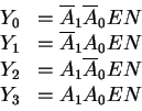
Example. Consider the 2-4 (n=2) decoder specified in the truth table:
| EN | A1 | A0 | Y3 | Y2 | Y1 | Y0 |
| 0 | X | X | 0 | 0 | 0 | 0 |
| 1 | 0 | 0 | 0 | 0 | 0 | 1 |
| 1 | 0 | 1 | 0 | 0 | 1 | 0 |
| 1 | 1 | 0 | 0 | 1 | 0 | 0 |
| 1 | 1 | 1 | 1 | 0 | 0 | 0 |
The output functions are given by

Example. Decoders can be used
to implement combinational logic functions.
Consider the cannonical SOP expression
Encoders perform the function opposite to that of decoders. Encoders have up to 2n inputs and n outputs, and generate an n-bit word for each of the inputs.
In priority encoders, any number of the inputs can be active, so a priority scheme selects a particular input line.
An n-m encoder block is shown in Figure 39.
Here,
![]() ,
EI denotes input enable, OE
denotes output enable, which together with GS is
used for cascading.
,
EI denotes input enable, OE
denotes output enable, which together with GS is
used for cascading.
A truth table indicating how the priority scheme is implemented is:
| EI | I2 | I1 | I0 | GS | Y1 | Y0 | EO |
| 0 | X | X | X | 0 | 0 | 0 | 0 |
| 1 | 1 | X | X | 1 | 1 | 1 | 0 |
| 1 | 0 | 1 | X | 1 | 1 | 0 | 0 |
| 1 | 0 | 0 | 1 | 1 | 0 | 1 | 0 |
| 1 | 0 | 0 | 0 | 0 | 0 | 0 | 1 |
I2 has the highest priority, with code 11; second is I1, with code 10; and lowest is I0, with code 01. When the device is inactive, the code is 00.
ANU Engineering - ENGN3213