 |
Tri-state gates have additional circuitry via which the gate outputs can be enabled or disabled. This is very useful in digital systems where devices communicate via common wires called busses. Only one device can talk at a time; the others are disabled.
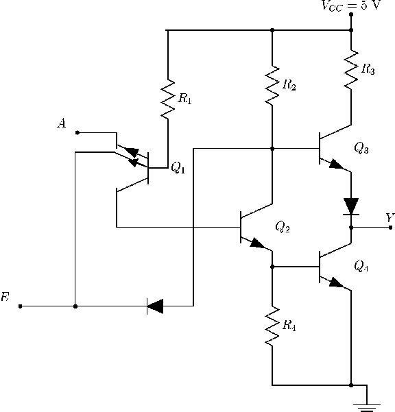
Figure 147 shows a tri-state TTL inverter. When E is H, the gate is enabled and behaves like a normal inverter; when E is L, the gate output is disabled, and there is a high impedance looking into the output (the ouput is essentially open-circuited).
The operation of the tri-state inverter is summarised in the table.
| Enable | Input | Output |
| L | X | Hi-Z |
| H | L | H |
| H | H | L |
ANU Engineering - ENGN2211