next up previous contents index

[ENGN2211 Home]

   
DC Bias

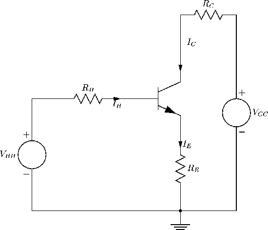
An important part of amplifier design is setting the DC bias point Q. In this section we look at a general bias network, Figure 107.


Figure 107: General DC bias network.
\begin{figure}
\begin{center}
\epsfig{file=images/bjtimg15.eps}\end{center}\end{figure}

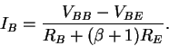
Applying KVL to the left loop gives

VBB = IB RB + VBE + IE RE .

Now since $I_E = (\beta + 1) I_B$ we can eliminate IE and solve for IB:

 \begin{displaymath}I_B = \frac{V_{BB} - V_{BE}}{R_B + (\beta + 1) R_E} .
\end{displaymath} (101)

Now $V_{BE} \approx 0.7$ V, and since VBB and the resistances are known, we can determine IB.

The right hand loop gives, using KVL,

VCC = IC RC + VCE + IE RE .

Now if $\alpha$ is close to 1, we assume $I_C \approx I_E$, and so eliminating IE and solving for IC we get

 \begin{displaymath}I_C = \frac{V_{CC} - V_{CE}}{R_E+R_C} .
\end{displaymath} (102)

This is the equation of the load line, Figure 108.


Figure 108: DC load line for BJT transistor circuit of Figure 107.
\begin{figure}
\begin{center}
\epsfig{file=images/bjtimg16.eps}\end{center}\end{figure}

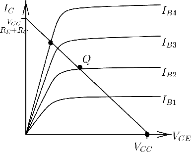
The operating point Q=QDC is determined from the load line and the collector characteristic curves, or via $I_C = \beta I_B$. Notice that in this analysis we have made (implicit) use of the DC model.

Example. 
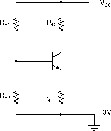
Find the DC operating point for the voltage divider bias network shown in Figure 109. Use $R_{B1}=470k\Omega$, $R_{B2}=18k\Omega$, $R_C=9.8k\Omega$, VCC=20 V, VBE=0.7 V, RE=0, and $\beta = 500$. Note that RE=0 in this example.


Figure 109: Voltage divider bias network.
\begin{figure}
\begin{center}
\epsfig{file=images/bjtimg17.eps}\end{center}\end{figure}

To solve this problem, we first replace the voltage divider VCC, RB1, RB2 by its Thevenin equivalent, which will be VBB in series with RB, as in Figure 107. Now

\begin{displaymath}R_B = R_{B1} \parallel R_{B2} = 17.34 \ k \Omega
\end{displaymath}

and

\begin{displaymath}V_{BB} = \frac{V_{CC}R_{B2}}{R_{B1} + R_{B2}} = 0.738 \ V
\end{displaymath}

So from (101) we get IB = 2.2 $\mu$A, and $I_C = \beta I_B = 1.1$ mA. Also from (102) we get VCE=9.22 V. Thus the DC operating point Q is IC = 1.1 mA, VCE=9.22 V, which is not far from midway along the load line (draw it!).

Note that absence of RE makes IB critically dependent on exact VBE. Using an emitter resistor RE improves the bias stability,   meaning robustness of the bias point with respect to parameter variations.


next up previous contents index

[ENGN2211 Home]

ANU Engineering - ENGN2211