next up previous contents index

[ENGN2211 Home]

Noninverting Amplifier

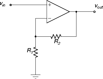
  A circuit diagram of an opamp in a noninverting amplifier configuration is shown in Figure 13.


Figure 13: Noninverting amplifier.
\begin{figure}
\begin{center}
\epsfig{file=images/opampimg1.eps}\end{center}\end{figure}

The input-output formula for the noninverting amplifier is

 \begin{displaymath}v_{out} = (1+\frac{R_2}{R_1}) v_{in} ,
\end{displaymath} (12)

as we saw earlier.

  Let's now derive this using the virtual model.

The key step is to apply KCL at the input nodes (we never apply KCL at the opamp output). The + node is connected to vin, so vin=v+. The virtual model says i+=0.

The - node is connected to two resistors, so we apply KCL:

\begin{displaymath}\frac{v_- - 0}{R_1} + \frac{v_- - v_{out}}{R_2} +i_- = 0 .
\end{displaymath}

The virtual model says i- = 0, and also v- = v+ = vin, so we get

\begin{displaymath}\frac{v_{in}}{R_1} + \frac{v_{in} - v_{out}}{R_2} = 0 .
\end{displaymath}

Solving for vout we get (12).

PSPICE file: noninv1.sch.


next up previous contents index

[ENGN2211 Home]

ANU Engineering - ENGN2211