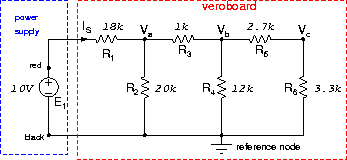
Construct the circuit of Figure 52
on the Veroboard provided. Since this is a soldering exercise, use the layout shown.
Ask the demonstrator to check your soldering, component values and circuit layout before you proceed.
2.
Connect the red wire of your circuit to +10Vdc,
the positive (RED) terminal,
and the black wire to the
negative (BLACK) terminal.
Switch the power supply on and adjust for 10Vdc (use a DVM).
3.
Measure the nodal
voltages Va, Vb, Vc and the source current IS and
complete Table 1.
Notify your demonstrator if the measured and calculated values differ by more than 10%.
4.
Sketch and label an equivalent circuit to that of Figure 52
which uses only one resistor.