

[ENGN2211 Home]
Load the PSPICE file
bjt-dc2.sch,
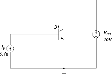
Figure 31.
Figure 31:
Circuit for measuring BJT characteristics.
 |
Exercise:
- 1.
- Simulate the circuit for the given setup. Is the
transistor Q1 on or off? Why?
- 2.
- We now want to obtain the family of characteristics,
IC vs VCE for various values of IB,
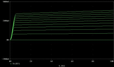
(like Figure 32, which shows IC as
a function of VCE; note that in this simulation
VCE=VCC).
We use the nested DC sweep feature:
VCC is set as the main sweep variable, ranging
from 0 V to 5 V in increments of 0.1 V.
IB is the nested sweep variable, ranging from
0 to 20  A in increments of 5
  A.
A.
Enable DC sweep and simulate again. Determine
the correct value of IB for each of the curves.
Lecture Notes : BJT Transistor Circuits : BJT Characteristics
- 3.
- Find the saturation and active regions
for a fixed value of IB.
- 4.
- Obtain a graphs of IC versus IB.
- 5.
- What is the current gain
 ?
?
Use the graphs to determine the ratio IC/IB in the active region for
several curves.
Figure 32:
BJT characteristics (IC versus VCE for several values of IB).
 |


[ENGN2211 Home]
ANU Engineering - ENGN2211

A in increments of 5
A.