

[ENGN2211 Home]
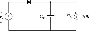
Load the PSPICE file
hwr.sch,
Figure 29.
Figure 29:
Half wave rectifier circuit.
 |
Exercise:
- 1.
- Simulate the circuit and obtain graphs of the source and load
voltages (transient).
Initially the circuit was set with C=1 fF  ,
to approximate the effect of no capacitor (unfiltered
rectifier).
Lecture Notes: Diode Circuits : Rectifiers
- 2.
- Measure the peak value of the load voltage, and find
the DC average load voltage.
- 3.
- Set C=10
 F, and simulate again.
What is the effect on the load voltage?
- 4.
- Measure the ripple voltage Vr, and the average DC load
voltage.
- 5.
- Experiment with different values of C and RL. What is
the effect of each?


[ENGN2211 Home]
ANU Engineering - ENGN2211

, to approximate the effect of no capacitor (unfiltered rectifier).