Home
Research
Publications
Teaching
Prospect Students
About Jon
Boards |
Dual Optic-Flow Integrated Navigation
Optic flow is the apparent visual motion seen by an observer when moving relative to a textured surface. This
motion can used to infer information about the state of the observer relative to that surface. This principle is used
heavily by insects, where optic flow is used to calculate odometry and regulate ground speed.
The advantages in using optic flow for motion measurement has made it attractive for implementation in robotic
vehicles. Recent advances in digital signal processors and CMOS cameras have provided a
means of embedding the devices on the same chip. This technology has been utilised by several manufacturers in
developing a chip that is dedicated to measuring displacement through optic flow. This has facilitated the use of
optic flow chips in robotics, as displacement measuring devices, and in odometry. These chips are
most commonly found in optical mice, and have been designed as stand-alone units.
 |
 |
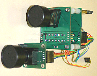
The first prototype of embedded real-time stereo visual odometry sensor developed in ANU. |
Optical-mouse chip (left) and MicroStrain 3DMG inertial measurement unit (right) used for
experiment. |
Results on Robot Manipulator
Illustrated in figure is the path taken by the end-effector of
the Scorbot (shown in blue). This has been reconstructed from the encoder outputs obtained during the experiment.
Although the path appears to be octagonal, the path was in fact a circle lying in the xy plane. The octagon appears
because the Scorbot outputs the encoder positions at a rate of 2Hz. The additional paths shown in the figure are
those traversed by the two optic flow chips. These plots are copies of the end-effector path, but translated using the
known displacement vectors for the two cameras with respect to the end effector.
 |
 |
The path taken by the end effector of a Scobot, a 6DoF manipulator (right), reconstructed from encoder outputs superimposed by the paths from dual-optic flow sensors. |
|
Deual Optic-Flow/INS Integrated Navigation
Scorbot manipulator has created lots of jerky accelerations due to its flexible stucture in joints and frictions. Thus, another arm stucture has been used for the experiment. The optic flow assembly and IMU were mounted to an
arm containing two pivoting joints, and rigidly mounted
to a workbench. The joints of each segment were vertical,
and contained well lubricated bushes with low amounts
of free play. The motion of the arm was constrained to the x − y plane of the navigation frame, which was
coincident with the IMU body frame at the commencement of the experiment.
|
Raw velocity estimate using pure integration
of accelerometers with raw attitude{left), and Raw Euler attitude estimate using pure integration of gyro (right). Both accelerometers and gyros are calibrated before run. |
|
Filtered INS velocity estimates using dual optic flow
sensors (left) and filtered Euler-angle estimates using dual optic
flow sensors (right). The perforomance improvements are apparant. |
Related Publications
- Kim, J. and Brambley, G., “Dual Optic-flow Integrated Inertial Navigation,” Australasian Conference on
Robotics and Automation (ACRA’07), Brisbane, Australian, Dec 10-12, 20076. [submitted]
|
|


