 |
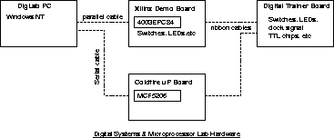
The hardware in the Digital Lab is organised as in Figure 61.
The Xilinx Demo Board hosts the Xilinx 4003EPC84 programmable logic chip (the 3000 series chip is not used in this course), and provides resources such as switches, LEDs, 7 segment displays, and parallel connection to a host PC. It has a cable connection to the Digital Trainer Board. The Digital Trainer Board houses a breadboard, switches, LEDs, 7 segment displays, clock generator, power supply, etc. The clock signal available on the trainer board is used to drive the FPGA, accessable via an input pin. The Motorola MCF5206 microprocessor is the heart of a microcomputer forming the coldfire single board computer (SBC). It also has connections to the Digital Trainer Board.
It is possible to create digital systems making use of the SBC, the FPGA, and resources on both the Xilinx Demo Board and the Digital Trainer Board, as well as discrete TTL circuitry on the breadboard.
The software in the Digital Lab is organised as in Figure 62.
The software in the Digital Lab facilitates the design, simulation and implementation of digital systems. This software is also installed in other Engineering PC labs.
ANU Engineering - ENGN3213