 |
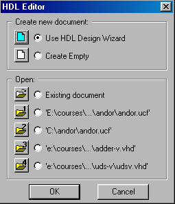
Next, open the HDL editor and select use HDL wizard, and click OK. Then use the wizard to create a skeleton file for a VHDL circuit with three inputs (A, B, C), and one output (X):
The following VHDL code skeleton should now appear in your HDL editor window:
library IEEE;
use IEEE.std_logic_1164.all;

entity andorv is
    port (
        A: in STD_LOGIC;
        B: in STD_LOGIC;
        C: in STD_LOGIC;
        X: out STD_LOGIC
    );
end andorv;

architecture andorv_arch of andorv is
begin
  -- <<enter your statements here>>
end andorv_arch;
Replace the comment with the VHDL code for X=AB+C as follows:
library IEEE;
use IEEE.std_logic_1164.all;

entity andorv is
    port (
        A: in STD_LOGIC;
        B: in STD_LOGIC;
        C: in STD_LOGIC;
        X: out STD_LOGIC
    );
end andorv;

architecture andorv_arch of andorv is
begin
  X <= (A and B) or C;
end andorv_arch;
Check the syntax:
SynthesisCheck Syntax
Next, in the HDL editor:
ProjectSee Figure 27.Add to Project
ANU Engineering - ENGN3213