GENERAL OBSERVATIONS
Radiation is the principle phenomenon leading to the transport of electromagnetic energy in free space. How to produce and detect it in a controlled way is explained in the chapter on antennas. Electromagnetic energy can only be transported over large distances and lead to a loss of energy from the system by radiation.
Concerning the mechanism by which electromagnetic radiation gains access to a system, the main effect to remember is skin effect. If we have a completely closed metallic box immersed in an electromagnetic field, the fields penetrate the surface of the box an exponential distance equal to the skin depth. The skin depth arises because the component of the electric field parallel to the surface of the box causes a current to flow that opposes penetration of the field. Skin effect is an inductive effect. The electric field is opposed by a changing magnetic field (that due to the current). The shielding is not perfect. Some field does enter if the conductivity is finite.
Using the formula for skin effect f = 30 MHz and Copper we obtain &delta = 12 microns. Thus for all intents and purposes skin depth shielding is perfect for usual metals. But be wary of low conductivity metals like stainless steel at low frequencies (below about 1 MHz for example).
A similar but unrelated effect is the following. Charge carriers can never exist uncompensated inside any conductor of any finite conductivity. (The currents that shield out electromagnetic fields in the skin effect carry zero net charge). Charges must lie on the surface of conductors if anywhere at all. This is because any charge inside a conductor decays exponentially in a time t = &epsilon o / &sigma . Given that &epsilon o = 8.89 x 10⁻¹² F/m, this time is very short (even at radiofrequency!).
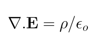
Example. Demonstrate it for yourselves! Using the divergence theorem,
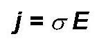
Ohms law for a conductor,
and charge continuity
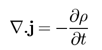
show that charge must decay away with the above time constant when placed uncompensated inside a metal.
This phenomenon which leads to the complete absence of charge is completely electrostatic in origin: it arises from Gauss' law, which states that charge is the source of electric field. Any electric field inside a conductor of finite conductivity must therefore be divergence (source) free. Physically this means that electric field lines inside conductors must close on themselves somewhere or terminate on the surface of the conductor.
Thus the first rule is that if your circuit is completely enclosed in a metal box, external RFI is impossible. Of course the problem is that a circuit completely enclosed in a box is pretty useless.
ENTRY MECHANISMS FOR UNWANTED RFIEven if you decide to power your circuit from a battery that is also enclosed inside the box, then sooner or later you are going to want to get the signals out and this is where the trouble begins. You'll also probably want to try out mains operated power supplies sometimes. We therefore have deal with the circuit entry points for RF pickup.
Power Supply Decoupling
The first problem is the external power supply. Often the power supply leads come from the outside world. In this case it is a simple matter to put an RF filter on the line as you enter the box.
Even so, RF signals generated in the circuit can cause pick up on power lines. It is therefore necessary to decouple all points in a circuit which are intended to be at DC and not at RF potential. This includes the power supplies and certain bias points. It is also a good idea to decouple for both low frequencies and high frequencies. This means a large Tantalum capacitor (these have low inductance) and a smaller (usually ceramic) capacitor of a suitable variety for the frequencies at hand. For example, at HF - VHF ordinary ceramic capacitors with leads and values from 10nF to 10 µ F will suffice. At VHF-UHF, surface mount capacitors are necessary.
Connectors
The most common unexpected problems arise with connectors or when testing exposed circuits. Let's consider connectors such as insulated BNCs. These are coaxial connectors in which there is an insulating gap between the coaxial cable and the box housing. The earth is insulated from the box allowing RF currents from outside to enter and "break the shield". The consequence is that RF currents flowing on the OUTSIDE of the coaxial cable (a virtual antenna) are injected into the inside earthing system of the box. The cure is to avoid using connectors like insulated BNCs that break the earth. In all interconnected RF systems there should be a contiguous shield. Use "normal earthed" BNCs at RF. Insulated BNCs are often used in low frequency circuits to avoid mains earth loops.
If on the other hand you think that you have a contiguous earth and yet RFI still occurs, then one has to question the quality of the connectors and cables. Braided coax can circumvent the skin effect at high frequencies due to its platted wire strands. This leads to leakage of signal to and from the cable.
External measurements
The above ideas are of limited utility when doing external measurements on exposed circuits (particularly antennas!) using such things as oscilloscope probes. In this case unwanted RFI enters your circuit and stuffs up your measurements. What's worse: it is unavoidable.
Measurements on an antenna are fraught with difficulty. I will not broach this issue here.
On the other hand if you are doing measurements on your circuit then consider enclosing the circuit inside a metal box and using coax to connect to the external measuring instruments. Let's face it: your circuit under test is being designed to go into some sort of box once testing is complete. The problem with this is that you are going to have to terminate the coax in a 50 &Omega impedance at the measuring instrument (usually a CRO or Cathode Ray Oscilloscope) (see the chapter on transmission lines).
I mention this because it is a common mistake to try and make measurements on exposed circuits. If you are just checking to see if the circuit is functional then fine, but oscilloscope probes, which are inherently external devices, are rarely up to the task at radiofrequency. The corollary unfortunately is that the circuit under test must be capable of feeding a 50 &Omega impedance in the first place. This is usually not a problem however as the circuit you are testing must be designed to interface to other devices with input and output impedances equal to some characteristic impedance like 50 &Omega .
The rule is this: all RF devices must be designed to input and output signals to and from other devices with defined characterisitic impedances such as 50 &Omega . All measurements where accuracy is important must be made with the DUT inside a shielded box and with external connections made on a fixed characteristic impedance such as 50 &Omega using coaxial cable. There will be plenty of opportunity to put these ideas to the test.