Transistor amplifiers are of course widely used. The aim of these notes take a look at a simple single-transistor BJT amplifier, and to let you experiment with it using spicecad. You will need to download the spice file bjt-amp1.sch.
To run the simulation in spicecad, startup spicecad and load
bjt1. (The transistor model file will be automatically read
in.)
Here is the circuit diagram:

If you run the simulation you will be able to observe a number of features of the circuit's operation.
The DC operating point can be determined by examining the voltage at the nodes. VB=9.84V, VE=9.03V, VC=21.02V. Compare this with the calculation done in class. The designer chooses the resistor values to bias the transistor for the desired AC amplification. If well designed, the amplifier can amplify input signals and produce an output with a minimum of distortion, so that the output faithfully reproduces the input signal but with larger amplitude. However, in general it is not possible to achieve perfect amplification without distortion, due to the real nonlinear nature of the transistor device. This example illustrates some of the distortion effects.
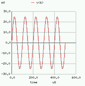
The input signal is a sinusoid of magnitude 25mV and frequency 10kHz:
Vg(t) = 25 cos(2pi 10,000 t) mV
The input waveform looks like:

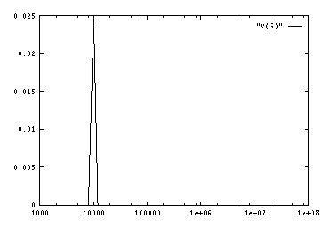
In the frequency domain, a pure sinusoid looks like a peak at the frequency of the sinusoid (in this case 10kHz):
Notice the capacitor connecting the source to the base of the transistor. This has the effect of providing an open circuit to DC, but providing an AC signal path (almost short circuit to AC if the frequency is high enough, since Z_C=1/(jwC), which decreases as the frequency w=2pi f increases). The ouput load resistor is connected to the transistor collector via a coupling capacitor for the same reasons. In this way the DC biasing of the transistor is not affected by the connection of AC sources and AC-coupled loads. The output voltage looks like
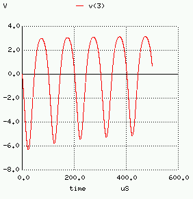
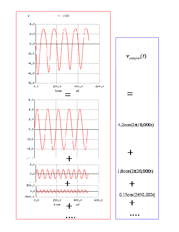
Note that the magnitude of the output voltage ranges between about -5V and +3V, which is significantly larger than the input source voltage. What is the value of the gain approximately? Notice also that the output voltage is distorted, i.e. not a perfect sinusoid. In fact the Fourier Transform of the output voltage looks like:
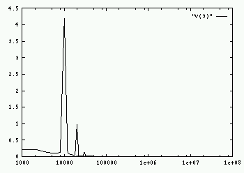
In this case, the Fourier Transform illustrates that the output waveform is the sum of sinusoids, called a Fourier Series:
v_output(t) = 4.2 cos(2pi 10,000 t) + 1.0 cos(2pi 20,000 t) + 0.15 cos(2pi 30,000 t) + ......
This sum consists of sinusoids at the fundamental frequency 10kHz, plussinusoids at harmonic frequencies 20kHz, 30kHz, 40kHz, etc.
In amplifier design, designers usually try to minimize the harmonics caused by nonlinearities. Total harmonic distortion is a commonly used performance parameter (you may see this quoted in hi-fi specs). In synthesizers, designers may wish to introduce harmonics to create sound effects.
Last updated: February 25, 1999 / Matt James