The hybrid combiner is a broadband adder subtractor circuit used to split and combiner RF signals. It is related to the 3 dB hybrid which is based on transmission lines and is most commonly used in high power broadband applications. The circuit equivalent of the hybrid combiner is shown in the figure. It is based on a trifilar winding and is connected with the winding senses shown.
One may imagine that the input voltages v1 and v2 are to be split into sum and difference signals to eliminate common mode signals (signals common to both sources 1 and 2 and difference signals, those not in common with 1 and 2. The application we have already seen but not studied is the voltage probe which consists of two heads, one which samples one point and the one which samples another point. The difference signals between these two heads is the desired voltage.
Many effects conspire to falsify a measurement. For example suppose that one head is sampling a voltage in a circuit and the other is connected to a near-by ground in the circuit. Both heads and the cables that run to them could be intercepted by RFI before the voltage is measured. If this is the case it is no good to short the earthed probe head at the measuring instrument, say an osclloscope. This is because the shorted head will provide no signal and the other, connected to the point in the circuit, will bare an unspecified combination of the signal under measurement and the pick-up. The solution is to assume that if both heads and cables are close together then they will pick-up identical RFI. If the two signals are then subtracted properly then the desired difference signal can be measured. This also shows the use of differential measurements (ones that don't involve earth).
We now investigate how to do the differential measurement properly. The following is the simplest transmission line transformer (broadband) hybrid combiner. We will analyse the circuit.
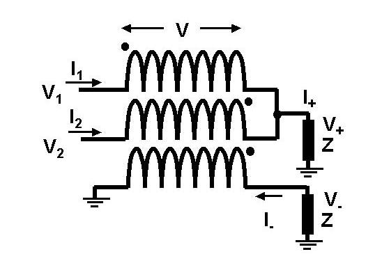
Assuming that the impedance of the individual windings is much greater than that of the impedances connected to the ports, we know that I1 - I2 + I- = 0. If V is the voltage drop across the windings, then
(1) V1 - V = V+
(2) V2 + V = V+
(3) V- = V
Therefore,
(4) V+ = (V1 + V2)/2
(5) V- = (V1 - V2)/2
which show that adding and subtracting work OK. But it is not even the most important thing! Read on. Moreover,
(6) I+ = I1 + I2
(7) I- = I2 - I1
(8) V+ = Z(I1 + I2)
(9) V- = Z(I1 - I2)
Using (4),(5) and (8),(9) we obtain,
V1 = 2ZI1
V2 = 2ZI2
These show that the input impedance seen at the two input ports is twice that at each of the output ports. Most importantly, the input ports are completely blind to each other. They donot cross-talk with each other. Often this simple fact is overlooked when transformers are employed in adder/ subtractor circuits. Why is this important? It is important because, as you know by now, input ports have to be terminated and this cannot be achieved if different input ports cross-talk.
There are two disadvantages of this circuit as it stands. Firstly, the impedance of the system is transformed on passing through the combiner. This is a disadvantage if operation on a unique impedance is desired. Secondly, currents are added without attention to phase balance. For example the currents, I1 and I2 are added at opposite ends of the transformer. This means that one is delayed along the transmission line while the other is not. If the winding length is significant in comparison to a wavelength this will directly lead to errors. In high power applications, this can be a severe limitation since components necessarily get larger and windings longer.
A simple solution to the latter problem is the following circuit.
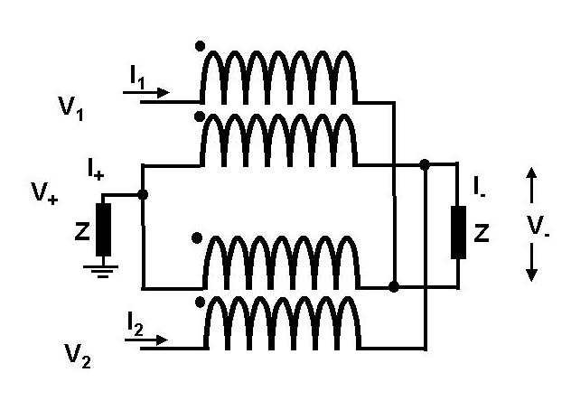
In this combiner there are now two separate bifilar transformers wound on separate cores. Notice that each of these could be a commercial coaxial cable to eliminate wire effects. The impedance here is still 2Z at the input but now the phase imbalance problem has been eliminated. It is also possible however to do a makeover of this circuit using a pair of 2:1 baluns at the input (G.G. Borg and T. Jahreis. "Radio-frequency power combiner for cw and pulsed applications" Rev. Sci. Int. 65(2) pp. 449-452 (1994)).
Commercially, high power combiners (the "3dB hybrids") generally use a different approach based on 1/4 wave transmission line sections that transform impedances so as to provide a uniform system impedance. At first sight these devices may seem narrow band but sections can be added to extend the bandwidth. In the high power combiner application, the aim is to put all of the power out the sum port. Nonetheless, proper operation requires that a load be connected at the difference port. This is needed to maintain a match at the inputs should either input transmitters go down or cease to be cophased. The difference port is commonly referred to as a "reject load" and under normal operating conditions it absorbs no popwer. For (not much) more information see 6.